How I setup my lights – The megatree

This is the second post in my series on how I setup my christmas lights

Links to rest of series:

This post focuses on the main megatree.

The megatree is made from 13 strings of 50 pixels each (configured in 6 pairs + one that then leads into the star at the top) At the top of the tree is a piece of wood screwed into the tree. Under this block of wood there are 13 eyelets which the strings are cable-tied to. At the bottom each string is pegged to the ground (with cable-tie providing tension)
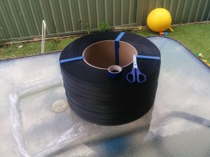
Pixel strings are not strong enough to support themselves at tension (and they would twist around so not always face outwards) To fix this I bought a roll of packaging tape and drilled holes in it at regular intervals. I would drill 56 holes and then cut the tape. This allowed my to double-back the tape for 3 pixels at each end – making a nice strong loop to use for attaching to top/bottom of tree.
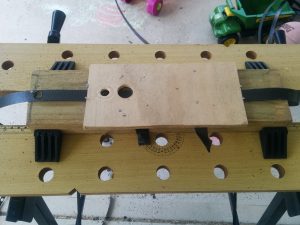
This is the little jig I made up so that the holes would be the same distance apart – with 13 strings of 56 holes each that meant 728 holes drilled by hand
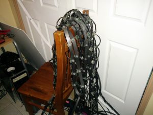
This shows the result of pushing the pixels through a couple of the strips. Doesn’t look too neat here but looks good once hung up. By having all the pixels poking through the strip I can make sure they are all facing the same way.

How I setup my lights – The controllers

In the last few weeks I’ve had a number of people asking about how the light show is done so I thought it might be nice to document how my lights are setup during the day using photos.

To see the display in action and to download all of the xLights sequences see the 2016 Debenham Lights post.

I’m going to write a series of posts showing how the controllers are setup, how the megatree is setup etc

Links to rest of series:

First up is how my controllers are installed

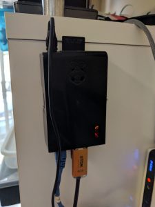
Everything is controlled by a copy of FPP running on a single RaspberryPi (original model). This sits in my home office and is connected to the FM transmitter via USB-Audio dongle. It is also connected to a network switch outside via a wired network cable
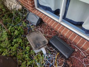
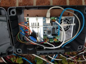
Outside there are two controllers in front of house
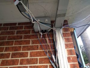
Then there is a controller fixed to the wall of the carport
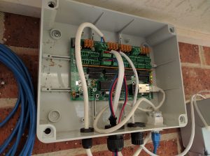
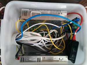
The carport box contains a Sandevices e682 which runs all the 12V pixel strips (such as carport, roof, arches and small christmas trees). Power for this controller comes from a 12V power supply in a separate box on the ground.
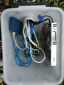
In this box is a E682 controller, 5V power supply and network switch.
This controller looks after the pixels in the main part of the yard – such as the megatree, candy canes and window surrounds
This box contains my old Renard 64XC controller. This has been converted to work via DMX and controls the two AC devices in my display (the tune-to sign and the inflatable santa)
This box contains a Pixlite4 and 5V power supply. It is used to control the singing tree, pixel items on the roof and the spiral tree

2016 Christmas Lights

All my sequences for this year are sitting at
https://www.adebenham.com/lights/xLights-2016/
If you wish to use them on your own display you will probably need my xlights_rgbeffect.xml to import them properly.

There are videos for them all now on Youtube and on facebook/

Everything is awesome:


xLights sequence download
Edited music download

Christmas parody mashup


xLights sequence download
Edited music download

Star Wars funk (thanks to loganc):


xLights sequence download
Edited music download

Carol of the Bells:


xLights sequence download
Edited music download

Let it Snow (thanks to loganc again):


xLights sequence download
Edited music download

Light of Christmas:


xLights sequence download
Edited music download

What does the Fox say:


xLights sequence download
Edited music download

Pokemon Theme song:


xLights sequence download
Edited music download

Pen Pineapple Apple Pen song:


xLights sequence and music download

Technical Details

For those that are interested this is all controlled by two Sandevices E682’s and an Advatek Pixlite4 sitting in large plastic tubs.

All the sequences were created in xLights running on Linux – and the show is controlled by FPP running on a Raspberry Pi

Christmas Lights

Each year I setup a display of Christmas lights in Narara.

This year (2015) I pretty much started from scratch as I moved to all pixels (each light is individually controlled)

Here are videos of my lights this year.

Jingle Bells pon de Floor

Light Of Christmas

What’s This

Wizards of Winter

Technical Details

For those that are interested this is all controlled by a Sandevices E682 and Advatek Pixlite4 sitting in a large plastic tub.

IMG_20151127_140104

All the sequences were created in xLights running on Linux – and the show is controlled by FPP running on a Raspberry Pi

If anyone is interested in the sequences used here is a zip file containing all the sequences and my xlights_rgbeffects.xml file

2015_Sequences

Arduino controlled lights – The Hardware

Okay – now that I have a box it is time to wire it all up.

After playing around with various methods of switching I settled on a bunch of solid-state relays connected to the arduino.

The advantage of solid-state relays over mechanical onese are that they switched quicker, are less likely to arc and don’t require any additional components to up the voltage in order to throw them.  I ended up with a bunch of FSS1-102Z relays which can be bought from jaycar for about $12 each as part SY4088.

These relays can switch 250VAC happily with only a 5V switch current.  This means I could wire them straight to the arduino.

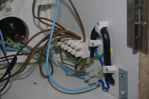
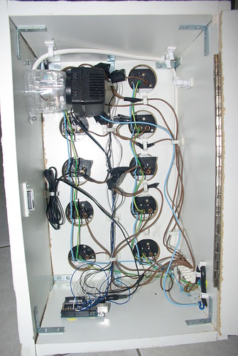
Power comes into the box from the side goes to two distribution blocks.

One block splits the earth (green) and neutral (blue) lines into three sets with one set going to the internal powerpoint (used to power the arduino plugpack) and the other two sets going up the left and right columns of power points.  Each powerpoint is linked to the one above it which helped to keep the wiring minimal and tidy.

The other, much larger, block provides a bunch of points for connecting the live (brown) wires.  From here power is sent to the internal powerpoint and one live wire to each row of powerpoints.
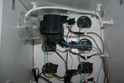
The live wires go up to each row and are split in two at the
last moment to each connect to one point on the load side of a relay. 
The other point on the load side of the relay connects to the live plug
on the powerpoint.

On the input side of the relays the negatives are all linked together and head down to ground on the arduino.

The positives are kept separate and go down to the digital outputs on the arduino.
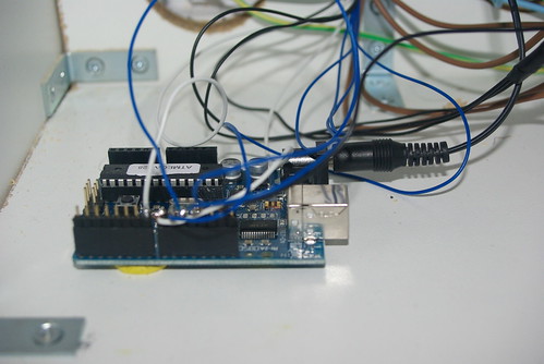
To make things a bit easier for testing I soldered each of the incoming lines to a row of pin headers.  This means I can quickly unplug/plug in the lines to the arduino in case I need to use it elsewhere.  It also helps to keep them in order ๐Ÿ™‚

Because this box is running 240V I added a small 240v light to the top of the box that is lit up whenever the box has power (even if the arduino is not running)  This just serves as a little warning.

The final result is seen below
Next up – the software!