Peggy 2 multi-game sketch v0.1

I had such fun writing the simple ‘snake’ game for my peggy 2 that I wrote a bunch of other games for it as well.

At the moment there is Snake, Breakout, Pong and Race.

You can download the sketch as peggy2_games_0.1.zip

When compiled it takes up 11432 bytes (it includes the ‘Tone’ library as I have started adding sound to the sketch – connect speaker to ADC5 to hear it)

Starting peggy2_game

Game menu

When you turn on the peggy2 a menu is presented displaying the available games – you can select from them using the up/down buttons and select with the ‘select’ or ‘any’ button on the left of the peggy2.  Only three game names fit on the screen at once so the entire display scrolls up/down when changing game (and highlights the current selection)  To change games press the reset button.

Playing the games

Snake

SnakeLevel select

When the game first starts you can choose which level to start at.  There are four different boards available – these boards are re-used in a loop just at a higher speed for later levels.

Eat the ‘apples’ to get points, don’t hit yourself or walls

Arrow buttons control movement of the snake.

Score screen

Pong

Pong game

Hit the ball back, get a point if the AI misses, AI gets the point if you miss

Left/right buttons control movement of the bottom paddle (one player only for the moment)

Break

Breakout game

Not much here yet, just displays a bouncing ball + blocks to hit

Left/right buttons control movement of the paddle

Race

Race game

Avoid the walls.  One point every 25 blocks driven past, walls get narrower every 25 points

Left/right buttons control movement of the car.

peggy2_games.zip

Peggy 2 Character display

As mentioned in the Peggy 2 Snake post I wrote a bunch of small utility functions to display a string on the peggy 2.

Each character is stored as a 24-bit number (held in a 32bit uint32) where each 4 bits indicates the on/off status for a row of 4 pixels. This results in allowing for a 4×6 pixel character

For example the character for the number ‘0’ is stored as 0x699996 which when spread out looks like:

0110
1001
1001
1001
1001
0110

By doing this I can store 0-9 and A-Z in only 144bytes.
To save RAM I put this in program memory using: PROGMEM prog_uint32_t chars[37] 

To write a character to the display I use a function “show_char” (note I use a special function ‘setPixel’ to set the individual pixels to a certain brightness level – but if you are not using grayscale then the call can be replaced by standard frame.SetPixel calls)

void show_char(char Character, byte x, byte y)
{
  byte charNum = 36;
  if ((Character >= '0') && (Character <= '9')) {
    charNum=Character-48;
  }
  if ((Character >= 'A') && (Character <= 'Z')) {
    charNum=Character-55;
  }
  unsigned long w;
  w = pgm_read_dword_near(chars + charNum);
  for (byte i=0; i<6; i++) {
    byte offset = 4*(5-i);
    byte b = w >> offset; // get four bits
    b=b & 0xF;
    if (b & B1000) setPixel(x,y+i,7);
    if (b & B0100) setPixel(x+1,y+i,7);
    if (b & B0010) setPixel(x+2,y+i,7);
    if (b & B0001) setPixel(x+3,y+i,7);
  }
}

To make things a bit easier to display a string I also created a quick wrapper function ‘write_string’

void write_string(char string[], byte x, byte y)
{
  byte i=0;
  while (string[i] != '\0') {
    show_char(string[i], x+(5*i), y);
    i++;
  }
}

Full usage/source can be found in the peggy 2 snake code

Peggy 2 Snake

For Christmas my wife gave me a peggy 2 and I finally got around to building it.

Peggy 2 running Snake

It has 24×25 White LEDs with a row of 25 Red LEDs across the bottom.

By having that bottom row a different colour I can use that section for displaying score or other information

The first application I wrote for it the good old game of ‘Snake’.  After writing a quick version of the game I realised it needed a bit more ‘flair’ and so added the ability to display an intro screen and score screen.  To make this easier I wrote a bunch of utility functions to display characters that are stored in an array. I’ll describe how this works in a separate post as Peggy 2 Character display.

The game has multiple levels (where walls are put up in different spots and the speed is increased).  All up the program takes up 5258 bytes so fits on an atmega168 with room to spare.

Source code is available as peggy2_snake.zip

If you don’t have all the leds soldered on you can change gameMinX, gameMaxX, gameMinY, gameMaxY and score* to set the area used to play/display score

Arduino controlled lights – The Hardware

Okay – now that I have a box it is time to wire it all up.

After playing around with various methods of switching I settled on a bunch of solid-state relays connected to the arduino.

The advantage of solid-state relays over mechanical onese are that they switched quicker, are less likely to arc and don’t require any additional components to up the voltage in order to throw them.  I ended up with a bunch of FSS1-102Z relays which can be bought from jaycar for about $12 each as part SY4088.

These relays can switch 250VAC happily with only a 5V switch current.  This means I could wire them straight to the arduino.

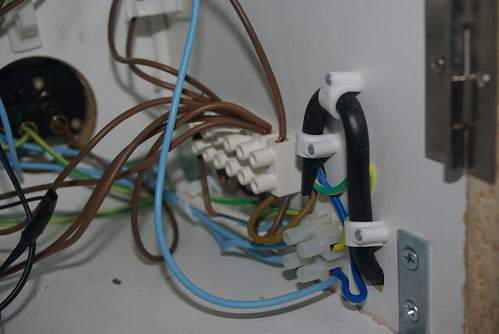
Power comes into the box from the side goes to two distribution blocks.

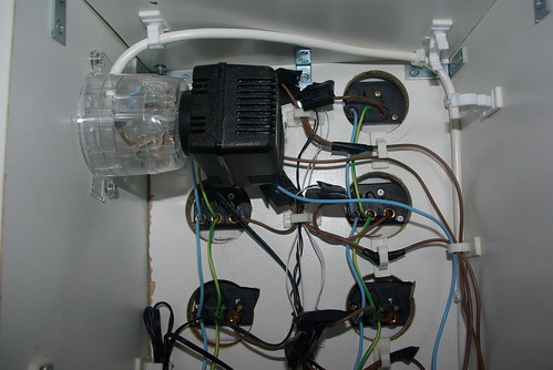
One block splits the earth (green) and neutral (blue) lines into three sets with one set going to the internal powerpoint (used to power the arduino plugpack) and the other two sets going up the left and right columns of power points.  Each powerpoint is linked to the one above it which helped to keep the wiring minimal and tidy.

The other, much larger, block provides a bunch of points for connecting the live (brown) wires.  From here power is sent to the internal powerpoint and one live wire to each row of powerpoints.

The live wires go up to each row and are split in two at the
last moment to each connect to one point on the load side of a relay. 
The other point on the load side of the relay connects to the live plug
on the powerpoint.

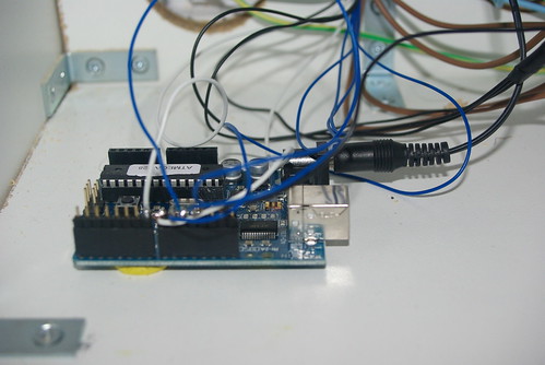
On the input side of the relays the negatives are all linked together and head down to ground on the arduino.

The positives are kept separate and go down to the digital outputs on the arduino.

To make things a bit easier for testing I soldered each of the incoming lines to a row of pin headers.  This means I can quickly unplug/plug in the lines to the arduino in case I need to use it elsewhere.  It also helps to keep them in order 🙂

Because this box is running 240V I added a small 240v light to the top of the box that is lit up whenever the box has power (even if the arduino is not running)  This just serves as a little warning.

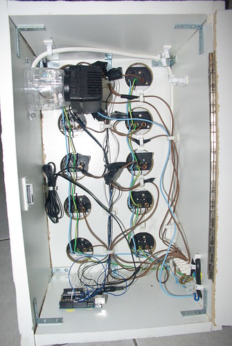
The final result is seen below

Next up – the software!

Arduino controlled lights – The Box

The aim was to start with 10 outlets and build out from there.

To make things easier I decided to make a box with room for 10 standard 240V wall powerpoints.

Each powerpoint is 117x70mm so allowing for two columns of five points (with space between each to allow for plugpacks)I ended up with a base of 250x460mm.  I ended up making the box 220mm deep so that it wouldn’t fall over (the exact dimension was mostly determined by the size of the piece of wood I had)

In the end I needed the following cuts:

  • 2 * 250×460 for front/back
  • 2 * 220×460 for sides
  • 2 * 250×210 for top/bottom

I cut the sides out of a sheet of melamine MDF and assembled by connecting with small right-angle brackets.  I then finished it up by applying some melamine lining to the exposed wood for aestetics.  The back panel was attached by a large hinge and a small handle was added.

Here is the final result: